25+ voltage to frequency converter block diagram
At much higher frequencies the transformer core size required drops dramatically. Working and Circuit diagram of a boost converter.
Digital Frequency Meter Construction Working And Its Applications
This is a typical step-up converter configuration.

. IN 45 V SDSS pin input voltage 3 6 V Delay pin voltage 3 15 V Flag pin voltage 03 45 V Feedback pin voltage 03 25 V Output voltage to ground steady-state 1 V Power dissipationLead temperature Internally limited KTW package Vapor phase 60 s 215 C Infrared 10 s 245 NDZ package soldering 10 s 260. Configure LMK with frequency to 12288 MHzREVAB. The block diagram of the digital storage oscilloscope is shown in the below figure.
These devices are used to know the current value and voltage values. Using a digital to analog converter the control voltage is provided to the frequency control. The hold sample is quantized into discrete value by the quantize blockAt last the encoder converts the discrete amplitude into a binary number.
Vref drives the non-inverting input of the operational amplifier. Why MOSFET Switch is Used in Boost Converter. Waveform reconstruction vertical plates horizontal plates cathode ray tube CRT horizontal amplifier time base circuitry trigger and clock.
This modulator can be used to control the op power of the supply. 24 GHz to 700 MHz Converter Overview. The voltage regulator using LM340 IC is the most used voltage regulator IC.
This is due to the mains fixed frequency of either 50 Hz Europe or 60 Hz United States. So as switching transistor MOSFETs are used. Determined by the internal reference the output of the comparator will go low.
A Boost Converter takes an input voltage and boosts it. Source and 08 A min. Water company in Brazil gets 25 energy savings and better uptime with ABB drives motors and digital powertrain solutions English - mp4 - Movie.
Sink peak current to drive the lower MOSFET of the half-bridge leg. The converter equipment and traction transformers have to accommodate different input frequencies and voltage ranging from as high as 50 Hz down to 167 Hz and rated up to 25 kV. Maximum supply voltage V.
And both the converter and the motor interfaces by the power source to provide changeable voltage frequency and current to the motor. The analog signal is first applied to the sample block where it is sampled at a specific sampling frequencyThe sample amplitude value is maintained and held in the hold block. The output voltage of the mixer is digitized.
A variable-frequency drive is a device used in a drive system consisting of the following three main sub-systems. This high gain helps the op. See Figure 191 PARAMETER TEST CONDITIONS MIN2 TYP3 MAX2 UNIT VOUT Output voltage VIN 8 V to 40 V ILOAD 20 mA to 1 A TJ 25C 3251 33 335 V TJ 40C to 125C 3201 3399 VIN.
A physically small transformer can handle power levels that would require a massive. Name Function 11 LVG Low-side gate-drive output. Typical system block diagram L6599 636 3 Typical system block diagram Figure 3.
3 Typical numbers are at 25C and represent the most likely norm. Step-Up Converter Note 4 Note. The control board contains a microprocessor that controls the transceiver converts the echo signals in a digital format as well usually via USB cable ensures the connection to a personal computer or laptop.
It might even be possible to hack the local oscillator out of an old 25 GHz MMDS downconverter and use that to drive an external frequency converter. For practical reasons this results in crankshaft rotational frequencies of either 25 Hz 1500 per minute or 30 Hz 1800 per minute. A VFD is a power converter that uses electronic circuits to convert a fixed frequency and fixed voltage into a variable frequency and variable voltage.
The power source in the above block diagram offers the necessary energy for the system. A high-voltage direct current HVDC electric power transmission system also called a power superhighway or an electrical superhighway uses direct current DC for electric power transmission in contrast with the more common alternating current AC systems. Refer the below table for frequency and offset values.
The pin is actively pulled to. It is an analog value. 75 Electrical Characteristics 33 V TJ 25C unless otherwise noted.
Y state if the resistor divider voltage at pin 5 is greater than the voltage in the non-inverting input which is 125V. The block diagram of the digital storage oscilloscope consists of an amplifier digitizer memory analyzer circuitry. The driver is capable of 03 A min.
Track SD30 J100 socket UTIL_3V3 33V. The AC electric motor used in a VFD system is usually a three-phase induction motorSome types of single-phase motors or synchronous motors can be. The block diagram of ADC is shown below which includes sample hold quantize and encoder.
In this configuration an op amp produces an output potential relative to circuit ground that is typically 100000 times larger than the potential difference between its input terminals. The step size is chosen dependent upon the set reference value. The engines crankshaft rotational frequency is chosen so that the mains frequency is a multiple of it.
The system level block diagram of the Evaluation Tool design is shown in the below figure. ACS880-1607LC DCDC converter units hardware manual English - pdf - Manual ACS880-307LCA018 diode supply units hardware manual English - pdf - Manual. Get 247 customer support help when you place a homework help service order with us.
Next with the freezer door open hold down the flapper door on the left hand side to un-block the optics beam More Products Features If the LED lights on the dimmer flickers first check if the lamp is dimmable The problem defective LED light module is on the fridge side located at the top I tried disconnecting power for 5-10 mins I tried. In other words its like a step up transformer ie it step up the level of DC voltage while transformer step up down the level of AC voltage from low to high while decreases the current from high to low while the supplied power is same. Typical system block diagram N.
Electric Drive Block Diagram Power Source. ACx580 DI5 frequency input. 245 GHz Bandpass Filter.
There are many stages of voltage gain for the op-amp used here. GBPPR Frequency Transverters for Wireless LAN Devices. An operational amplifier often op amp or opamp is a DC-coupled high-gain electronic voltage amplifier with a differential input and usually a single-ended output.
It even enables a motor to run above its rated speed by increasing the frequency. Most HVDC links use voltages between 100 kV and 800 kV. In this type of ADC converter comparison voltage is generated by using an integrator circuit which is formed by a.
However a 1100 kV link in China was. In general a boost converter needs a switching transistor for the operation of the device. Step size is the change in analog input to cause a unit.
SD30 U107 IP4856CX25 level-trans. Here is a simple 245 GHz bandpass filter you can build yourself for around. Since the speed of an induction motor depends on the supply frequency the VFD can be used to vary its speed.
We will guide you on how to place your essay help proofreading and editing your draft fixing the grammar spelling or formatting of your paper easily and cheaply. AC motor main drive controller assembly and driveoperator interface. GND revert to internal.
A microphone colloquially called a mic or mike m aɪ k is a transducer that converts sound into an electrical signalMicrophones are used in many applications such as telephones hearing aids public address systems for concert halls and public events motion picture production live and recorded audio engineering sound recording two-way radios megaphones and radio and. As shown in the block diagram above the built-in reference voltage. Also considering the switching speed and cost these are extensively employed.
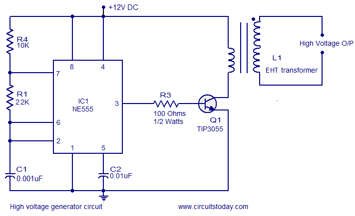
High Voltage Generator Circuit

Uc3845 Current Mode Pwm Controller Pinout Feature Datasheet

Frequency To Voltage Converter Circuit Electronics Circuit Circuit Voltage Converter
How To Derive Obtaining Isolated Semi Regulator Outputs From A Buck Regulator Quora
How To Convert A Varying Ac To A Constant Dc Quora

Frequency To Voltage Converter Circuit Diagram Applications Of Fv Converter Applications And Analog To Digital Converter Electronic Circuit Projects Circuit
Half Bridge Inverter Circuit Diagram Advantages Its Disadvantages
How Do The Components Of A Dc To Ac Static Converter Combine To Produce An Alternating Current Quora

Voltage To Frequency Converter Circuit Circuit Diagram Circuit Electronic Circuit Projects
Pin On Elektronika

Voltage To Frequency Converter Using Ad654 Electronic Circuit Projects Electronics Circuit Function Generator
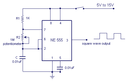
Variable Frequency Oscillator Circuit With Schematic

Voltage To Frequency Converter Circuit Using Ca3130 Basic Electronic Circuits Electronics Circuit Electronic Circuit Projects
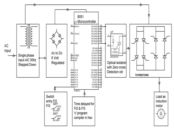
Buildig Of Single Phase Cycloconverter Using Thyristors And Applications
![]()
Dc To Ac Inverter Circuit Working Limitations And Applications
Analog To Digital Converter Block Diagram Types Its Applications
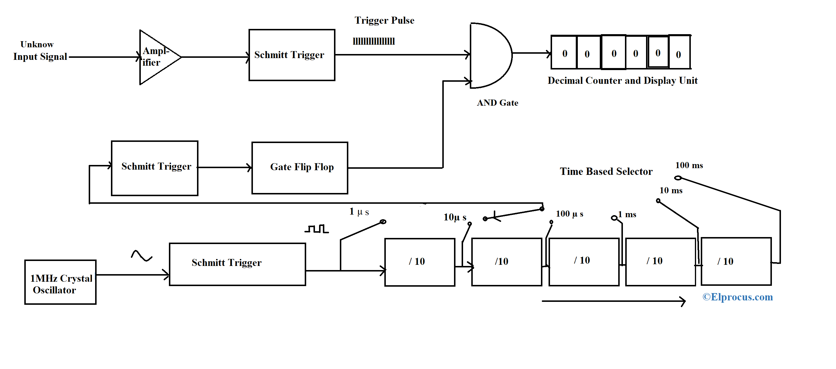
Frequency Counter Block Diagram Circuit Types And Its Applications